
مقدمه
در این آموزش با سنسور رنگ TSC320 آشنا شده و یاد می گیرید که چگونه این سنسور را به آردوینو متصل کرده و از آن در تشخیص رنگ استفاده کنید.
در انتهای این آموزش یک ایده ی جذاب برای ساخت قلم اسکن رنگ، مطرح شده است. با این قلم می توانید رنگ اجسام محیط را اسکن کرده و با آن رنگ، شروع به نقاشی روی یک نمایشگر کنید.
آنچه در این آموزش یاد می گیرید
- آشنایی با سنسور TCS230
- آشنایی با نحوه ی راه اندازی این ماژول با آردوینو و تشخیص رنگ های مختلف با آن
سنسور TSC230 چیست؟
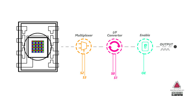
تراشه ی TSC230 دارای یک آرایه ی 8×8 از فوتو دیود های سیلیکونی است که از آن ها برای تشخیص رنگ استفاده می کند. از این 64 فتو دیود، 16 عدد دارای فیلتر رنگ قرمز، 16 عدد دارای فیلتر رنگ سبز، 16 عدد دارای فیلتر رنگ آبی و 16 عدد بدون فیلتر هستند.
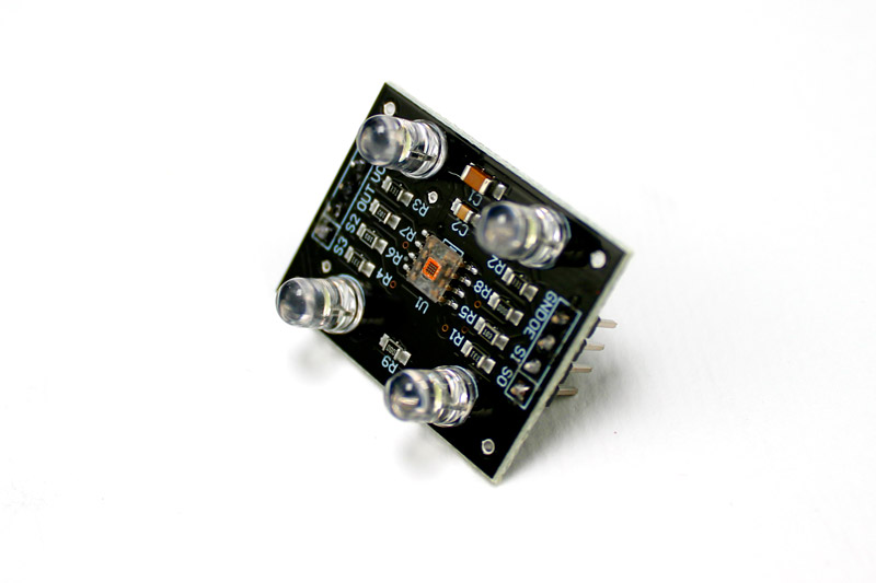
ماژول TCS230 دارای 4 ال ای دی سفید رنگ است. فوتو دیود ها، بازتاب نور این الی ای دی ها را از سطح جسم دریافت می کنند و بسته به رنگی که دریافت کرده اند، یک جریان الکتریکی تولید می کنند.
در داخل این سنسور علاوه بر فوتو دیودها، یک مبدل جریان به فرکانس نیز وجود دارد. این مبدل، جریان تولید شده توسط فوتو دیود ها را به فرکانس تبدیل می کند.
خروجی این ماژول به صورت فرکانس با پالس های مربعی با duty cycle 50 درصد است.
بهترین بازه ی اندازه گیری این سنسور حدود 2 تا 4 سانتی متر است.
پایه های سنسور


این سنسور 4 پایه ی کنترلی دارد. پایه های S0 و S1 برای کنترل مقیاس فرکانس خروجی (OUTPUT FREQUENCY SCALING) و پایه های S2 و S3 برای انتخاب نوع فوتو دیود (قرمز، سبز، آبی و بدون فیلتر) است.
مدار مبدل جریان به فرکانس، دارای مقسم های فرکانس (frequency dividers) است. با پایه های کنترلی S0 و S1 می توانید این مقسم فرکانسی را کنترل کنید.
| S0 | S1 | OUTPUT FREQUENCY SCALING (f0) | S2 | S3 | PHOTODIODE TYPE | |
|---|---|---|---|---|---|---|
| L | L | Power down | L | L | Red | |
| L | H | 2% | L | H | Blue | |
| H | L | 20% | H | L | Clear (no filter) | |
| H | H | 100% | H | H | green |
برای مثال، اگر بخواهید مقدار رنگ آبی یک جسم را اندازه گیری کنید، باید همزمان پایه ی S2 را LOW و S3 را HIGH کنید.
لوازمی که به آن احتیاج دارید

قطعات مورد نیاز
نرم افزارهای مورد نیاز
راه اندازی سنسور تشخیص رنگ TCS230 با آردوینو
سیم بندی
طبق مدار زیر، سنسور را به آردینو متصل کنید.

کد
کد زیر، سیگنال خروجی برای هر سه رنگ قرمز، سبز و آبی را اندازه گیری می کند و نتیجه را روی پورت سریال نمایش می دهد.
/*

  TCS230 color recognition sensor

  modified on 7 May 2019

  by Mohammadreza Akbari @ Electropeak

  Home


Color Sensor      Arduino

-----------      --------

 VCC               5V

 GND               GND

 s0                8

 s1                9

 s2                10

 s3                11

 OUT               12

 OE                GND

*/

const int s0 = 8;

const int s1 = 9;

const int s2 = 10;

const int s3 = 11;

const int out = 12;

// LED pins connected to Arduino

int redLed = 2;

int greenLed = 3;

int blueLed = 4;

// Variables

int red = 0;

int green = 0;

int blue = 0;


void color()

{

  digitalWrite(s2, LOW);

  digitalWrite(s3, LOW);

  //count OUT, pRed, RED

  red = pulseIn(out, digitalRead(out) == HIGH ? LOW : HIGH);

  digitalWrite(s3, HIGH);

  //count OUT, pBLUE, BLUE

  blue = pulseIn(out, digitalRead(out) == HIGH ? LOW : HIGH);

  digitalWrite(s2, HIGH);

  //count OUT, pGreen, GREEN

  green = pulseIn(out, digitalRead(out) == HIGH ? LOW : HIGH);

}


void setup()

{

  Serial.begin(9600);

  pinMode(s0, OUTPUT);

  pinMode(s1, OUTPUT);

  pinMode(s2, OUTPUT);

  pinMode(s3, OUTPUT);

  pinMode(out, INPUT);

  pinMode(redLed, OUTPUT);

  pinMode(greenLed, OUTPUT);

  pinMode(blueLed, OUTPUT);

  digitalWrite(s0, HIGH);

  digitalWrite(s1, HIGH);

}


void loop()

{

  color();

  Serial.print("R Intensity:");

  Serial.print(red, DEC);

  Serial.print(" G Intensity: ");

  Serial.print(green, DEC);

  Serial.print(" B Intensity : ");

  Serial.print(blue, DEC);

  //Serial.println();


  if (red < blue && red < green && red < 20)

  {

   Serial.println(" - (Red Color)");

   digitalWrite(redLed, HIGH); // Turn RED LED ON

   digitalWrite(greenLed, LOW);

   digitalWrite(blueLed, LOW);

  }


  else if (blue < red && blue < green)

  {

   Serial.println(" - (Blue Color)");

   digitalWrite(redLed, LOW);

   digitalWrite(greenLed, LOW);

   digitalWrite(blueLed, HIGH); // Turn BLUE LED ON

  }


  else if (green < red && green < blue)

  {

   Serial.println(" - (Green Color)");

   digitalWrite(redLed, LOW);

   digitalWrite(greenLed, HIGH); // Turn GREEN LED ON

   digitalWrite(blueLed, LOW);

  }

  else{

  Serial.println();

  }

  delay(300);

  digitalWrite(redLed, LOW);

  digitalWrite(greenLed, LOW);

  digitalWrite(blueLed, LOW);

 }
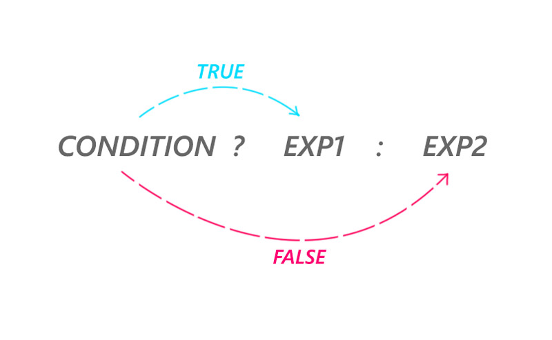
دستور شرطی
کالیبره کردن سنسور تشخیص رنگ TCS230
برای کالیبره کردن سنسور نیاز به یک جسم با رنگ سفید دارید.
تابع calibrate عملیات کالیبره کردن سنسور را انجام می دهد. برای کالیبره کردن سنسور کافیست در پنجره سریال، کاراکتر “c” را وارد کنید. سپس باید اجسام رنگی را از سنسور دور کرده و مجددا “c” را وارد کنید. حالا جسم سفید رنگ را نزدیک سنسور بگیرید و مجددا “c” را وارد کنید.
در پایان کالیبره کردن، اگر جسم سفید رنگ را مقابل سنسور نگه دارید، برای هر سه رنگ قرمز و سبز و آبی باید مقدار 255 (یا نزدیک به 255) را در پنجره ی سریال مشاهده کنید.
نحوه ی کار این تابع بسیار ساده است. این تابع حداقل و حداکثر تغییرات فرکانس خروجی سنسور را در محیط بدون رنگ و رنگ سفید محاسبه و ذخیره می کند.
سپس در بخش loop با دستور map بازه ی حداقل و حداکثر تغییرات را روی بازه ی 0 تا 255 (یا هر بازه ای که شما تعریف کنید) مقیاس (map) می کند.
اگر با دستور map آشنا نیستید به اینجا مراجعه کنید.
کد
/*

  // TCS230 color recognition with calibration

  modified on 7 May 2019

  by Mohammadreza Akbari @ Electropeak

  Home


  Color Sensor      Arduino

  -----------      --------

  VCC               5V

  GND               GND

  s0                8

  s1                9

  s2                10

  s3                11

  OUT               12

  OE                GND

*/

const int s0 = 8;

const int s1 = 9;

const int s2 = 10;

const int s3 = 11;

const int out = 12;

// LED pins connected to Arduino

int redLed = 5;

int greenLed = 6;

int blueLed = 3;

// Variables

int red = 0;

int green = 0;

int blue = 0;


// Calibrated value

int cal_min = 5;

int cal_max_r = 50;

int cal_max_g = 50;

int cal_max_b = 50;


void calibrate() {

  Serial.println("Clear sensor area. Then enter c again");

    while (Serial.read() != 'c') {

      //do nothing

      ;

    }

    color();

    cal_max_r = red;

    cal_max_g = green;

    cal_max_b = blue;

    Serial.println("Put white color infront of sensor, Then enter c again");

    while (Serial.read() != 'c') {

      //do nothing

      ;

    }

    color();

    cal_min = (red + green + blue) / 3;

    Serial.println("calibrated successfully.");

    delay(300);

}


void color() {

  digitalWrite(s2, LOW);

  digitalWrite(s3, LOW);

  //count OUT, pRed, RED

  red = pulseIn(out, digitalRead(out) == HIGH ? LOW : HIGH);

  digitalWrite(s3, HIGH);

  //count OUT, pBLUE, BLUE

  blue = pulseIn(out, digitalRead(out) == HIGH ? LOW : HIGH);

  digitalWrite(s2, HIGH);

  //count OUT, pGreen, GREEN

  green = pulseIn(out, digitalRead(out) == HIGH ? LOW : HIGH);

}


void setup()

{

  Serial.begin(9600);

  pinMode(s0, OUTPUT);

  pinMode(s1, OUTPUT);

  pinMode(s2, OUTPUT);

  pinMode(s3, OUTPUT);

  pinMode(out, INPUT);

  pinMode(redLed, OUTPUT);

  pinMode(greenLed, OUTPUT);

  pinMode(blueLed, OUTPUT);

  digitalWrite(s0, HIGH);

  digitalWrite(s1, HIGH);

}


void loop()

{

  color();

  if (Serial.read() == 'c') {

    calibrate();

  }


  red = map(red, cal_min, cal_max_r, 255, 0);

  green = map(green, cal_min, cal_max_g, 255, 0);

  blue = map(blue, cal_min, cal_max_b, 255, 0);

  Serial.print("R Intensity:");

  Serial.print(red);

  Serial.print(" G Intensity: ");

  Serial.print(green);

  Serial.print(" B Intensity : ");

  Serial.println(blue);

  delay(200);

}
ساخت قلم اسکن رنگ با سنسور TCS230 و آردوینو
اگر از آردوینو UNO استفاده می کنید، باید سنسور رنگ را با سیم به پایه های آردوینو لحیم کنید. ولی اگر از آردوینو MEGA استفاده می کنید، می توانید از پایه های انتهای برد برای اتصال سنسور رنگ استفاده کنید
اگر برای اولین بار است که با نمایشگر کار می کنید، می توانید آموزش راه اندازی نمایشگر را در اینجا مشاهده کنید.
کد زیر یک صفحه ی نقاشی را روی نمایشگر ایجاد می کند. رنگ اولیه ی قلم قرمز است. با نگه داشتن کلید و نزدیک کردن سنسور تشخیص رنگ به جسم مورد نظر، رنگ آن انتخاب می شود و رنگ قلم شما به رنگ جسم مورد نظر تغییر می کند.
سیم بندی

کد
/*

  TCS230 color picker + paint

  Modified on 8 May 2019

  By Mohammadreza Akbari @ Electropeak

  Home


  Color Sensor      Arduino

  -----------      --------

  VCC               5V

  GND               GND

  s0                5V

  s1                5V

  s2                10

  s3                11

  OUT               12

  OE                GND

*/


#include <Adafruit_GFX.h>       // Core graphics library

#include <Adafruit_TFTLCD.h>   // Hardware-specific library

#include <TouchScreen.h>


#if defined(__SAM3X8E__)

#undef __FlashStringHelper::F(string_literal)

#define F(string_literal) string_literal

#endif


//LCD

#define YP A3  // must be an analog pin, use "An" notation!

#define XM A2  // must be an analog pin, use "An" notation!

#define YM 9   // can be a digital pin

#define XP 8   // can be a digital pin


#define TS_MINX 150

#define TS_MINY 120

#define TS_MAXX 920

#define TS_MAXY 940


// For better pressure precision, we need to know the resistance

// between X+ and X- Use any multimeter to read it

// For the one we're using, its 300 ohms across the X plate

TouchScreen ts = TouchScreen(XP, YP, XM, YM, 300);


#define LCD_CS A3

#define LCD_CD A2

#define LCD_WR A1

#define LCD_RD A0

// optional

#define LCD_RESET A4


// Assign human-readable names to some common 16-bit color values:

#define BLACK   0x0000

#define BLUE    0x001F

#define RED     0xF800

#define GREEN   0x07E0

#define CYAN    0x07FF

#define MAGENTA 0xF81F

#define YELLOW  0xFFE0

#define WHITE   0xFFFF


Adafruit_TFTLCD tft(LCD_CS, LCD_CD, LCD_WR, LCD_RD, LCD_RESET);


#define BOXSIZE 40

#define PENRADIUS 3

int oldcolor, ccolor;


#define MINPRESSURE 10

#define MAXPRESSURE 1000


//Color sensor

const int s2 = 10;

const int s3 = 11;

const int out = 12;


const int button = 13;


// Color variables

int red = 0;

int green = 0;

int blue = 0;


// Calibrated value

int cal_min = 5;

int cal_max_r = 50;

int cal_max_g = 50;

int cal_max_b = 50;


uint16_t my_color;


void calibrate() {

  Serial.println("Clear sensor area. Then enter c again");

  while (Serial.read() != 'c') {

    //do nothing

    ;

  }

  color();

  cal_max_r = red;

  cal_max_g = green;

  cal_max_b = blue;

  Serial.println("Put white color infront of sensor, Then enter c again");

  while (Serial.read() != 'c') {

    //do nothing

    ;

  }

  color();

  cal_min = (red + green + blue) / 3;

  Serial.println("calibrated successfully.");

  delay(300);

}


void color() {

  digitalWrite(s2, LOW);

  digitalWrite(s3, LOW);

  //count OUT, pRed, RED

  red = pulseIn(out, digitalRead(out) == HIGH ? LOW : HIGH);

  digitalWrite(s3, HIGH);

  //count OUT, pBLUE, BLUE

  blue = pulseIn(out, digitalRead(out) == HIGH ? LOW : HIGH);

  digitalWrite(s2, HIGH);

  //count OUT, pGreen, GREEN

  green = pulseIn(out, digitalRead(out) == HIGH ? LOW : HIGH);

}


void pick_color() {

  color();

  red = map(red, cal_min, cal_max_r, 255, 0);

  green = map(green, cal_min, cal_max_g, 255, 0);

  blue = map(blue, cal_min, cal_max_b, 255, 0);


  Serial.print("R Intensity:");

  Serial.print(red);

  Serial.print(" G Intensity: ");

  Serial.print(green);

  Serial.print(" B Intensity : ");

  Serial.println(blue);


  //my_color = tft.color565(abs(255 - red), abs(255 - green), abs(255 - blue));

  my_color = tft.color565(red, green, blue);

  tft.fillRect(0, 0, 6*BOXSIZE, BOXSIZE, my_color);


  delay(100);


}


void setup()

{

  Serial.begin(9600);

  tft.reset();

  delay(1000);

  uint16_t identifier = tft.readID();


  if (identifier == 0x9325) {

    Serial.println(F("Found ILI9325 LCD driver"));

  } else if (identifier == 0x9328) {

    Serial.println(F("Found ILI9328 LCD driver"));

  } else if (identifier == 0x7575) {

    Serial.println(F("Found HX8347G LCD driver"));

  } else if (identifier == 0x9341) {

    Serial.println(F("Found ILI9341 LCD driver"));

  } else if (identifier == 0x8357) {

    Serial.println(F("Found HX8357D LCD driver"));

  } else {

    Serial.print(F("Unknown LCD driver chip: "));

    Serial.println(identifier, HEX);

    Serial.println(F("If using the Adafruit 2.8\" TFT Arduino shield, the line:"));

    Serial.println(F("#define USE_ADAFRUIT_SHIELD_PINOUT"));

    Serial.println(F("should appear in the library header (Adafruit_TFT.h)."));

    Serial.println(F("If using the breakout board, it should NOT be #defined!"));

    Serial.println(F("Also if using the breakout, double-check that all wiring"));

    Serial.println(F("matches the tutorial."));

    return;

  }


  tft.begin(identifier);


  tft.fillScreen(BLACK);


  tft.fillRect(0, 0, 6*BOXSIZE, BOXSIZE, RED);

  my_color = RED;


  pinMode(s2, OUTPUT);

  pinMode(s3, OUTPUT);

  pinMode(out, INPUT);

  pinMode(button, INPUT_PULLUP);

}


void loop()

{

  if (Serial.read() == 'c') {

    calibrate();

  }


  while (digitalRead(button) == LOW) {

    pick_color();

  }


  TSPoint p = ts.getPoint();


  // if sharing pins, you'll need to fix the directions of the touchscreen pins

  //pinMode(XP, OUTPUT);

  pinMode(XM, OUTPUT);

  pinMode(YP, OUTPUT);

  //pinMode(YM, OUTPUT);


  // we have some minimum pressure we consider 'valid'

  // pressure of 0 means no pressing!


  if (p.z > MINPRESSURE && p.z < MAXPRESSURE) {

    /*

    Serial.print("X = "); Serial.print(p.x);

    Serial.print("\tY = "); Serial.print(p.y);

    Serial.print("\tPressure = "); Serial.println(p.z);

    */


    if (p.y < (TS_MINY-5)) { Serial.println("erase"); // press the bottom of the screen to erase tft.fillRect(0, BOXSIZE, tft.width(), tft.height()-BOXSIZE, BLACK); } // scale from 0->1023 to tft.width

    p.x = map(p.x, TS_MINX, TS_MAXX, tft.width(), 0);

    p.y = map(p.y, TS_MINY, TS_MAXY, tft.height(), 0);

    /*

    Serial.print("("); Serial.print(p.x);

    Serial.print(", "); Serial.print(p.y);

    Serial.println(")");

    */


    if (((p.y-PENRADIUS) > BOXSIZE) && ((p.y+PENRADIUS) < tft.height())) {

      tft.fillCircle(p.x, p.y, PENRADIUS, my_color);

    }

  }

}
تابع pick_color، در زمان فشردن کلید فراخوانی می شود و رنگ جسمی که در نزدیکی سنسور قرار دارد را می خواند. سپس رنگ قلم را به رنگ جسم تغییر می دهد.
یک گام جلوتر
- یک دستگاه انبارداری کوچک بسازید که قطعات لگو را با توجه به رنگ آن ها از یکدیگر جدا کند.


Comments (2)
سلام.برای اینکه کاری کنیم که این سنسور رنگ های دیگه مثلا زرد رو تشخیص بده باید چه کدی اضافه کنیم؟؟ ممنون
با سلام. از کد آموزش زیر استفاده کنید.
https://thecaferobot.com/learn/interfacing-tcs230-color-recognition-sensor-with-arduino-2/