

ویژگیهای مولد سیگنال موج مربعی SI5351
ماژول مولد سیگنال موج مربعی SI5351 کاربرپسند بوده و سیگنالهای دقیق و تنظیمپذیری تولید میکند. ویژگی اصلی SI5351، تولید سیگنالهای موج مربعی بسیار دقیق در محدوده فرکانس وسیع است، بنابراین کاربرد فراوانی دارد – از پروژههای رادیویی آماتور گرفته تا ایجاد ابزارهای الکترونیکی DIY. این ماژول با طراحی فشرده و رابط سادۀ خود، هم برای مبتدیان و هم برای افراد با تجربه مناسب است.
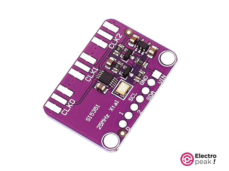
پیناوت مولد سیگنال موج مربعی SI5351
مولد سیگنال موج مربعی SI5351 هفت پین دارد:
- VIN (5V): ورودی منبع تغذیه برای ماژول BMP388 .
- GND: زمین.
- SCL: خط کلاک سریال برای ارتباط با میکروکنترلر.
- SDA: خط داده سریال برای پیکربندی تنظیمات ماژول.
- D0-D2: پینهای خروجی برای سیگنالهای موج مربعی تنظیمپذیر.
میتوانید پیناوت این ماژول را در تصویر زیر مشاهده کنید.

لوازمی که به آن احتیاج دارید
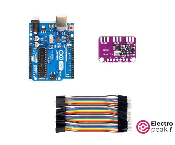
قطعات مورد نیاز
راهاندازی مولد سیگنال موج مربعی SI5351 با آردوینو
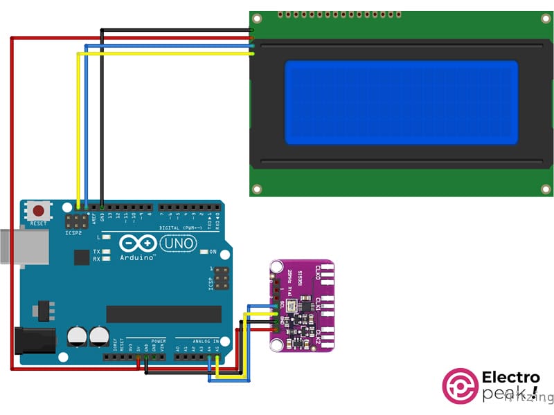
گام اول: مدار
مدار را مطابق با شکل زیر ببندید. (صفحه نمایش را در صورت نیاز استفاده کنید.)
گام دوم: نصب کتابخانه
گام سوم: کد
برای راهاندازی برد بدون نمایشگر، کد زیر را در آردوینو آپلود کنید.
/*
Create on January 27, 2024
Create by MohammedDamirchi base of https://github.com/adafruit/Adafruit_Si5351_Library
<blockquote class="wp-embedded-content" data-secret="804Lhnp2NH"><a href="https://electropeak.com/learn/">Home</a></blockquote><iframe loading="lazy" class="wp-embedded-content" sandbox="allow-scripts" security="restricted" style="position: absolute; clip: rect(1px, 1px, 1px, 1px);" title="“Home” — Electropeak" src="about:blank" data-secret="804Lhnp2NH" width="600" height="338" frameborder="0" marginwidth="0" marginheight="0" scrolling="no" data-rocket-lazyload="fitvidscompatible" data-lazy-src="https://electropeak.com/learn/embed/#?secret=vu3AQdKkI4#?secret=804Lhnp2NH"></iframe><noscript><iframe class="wp-embedded-content" sandbox="allow-scripts" security="restricted" style="position: absolute; clip: rect(1px, 1px, 1px, 1px);" title="“Home” — Electropeak" src="https://electropeak.com/learn/embed/#?secret=vu3AQdKkI4#?secret=804Lhnp2NH" data-secret="804Lhnp2NH" width="600" height="338" frameborder="0" marginwidth="0" marginheight="0" scrolling="no"></iframe></noscript>
*/
#include <Arduino.h>
#include <SPI.h>
#include <Adafruit_SI5351.h>
Adafruit_SI5351 clockgen = Adafruit_SI5351();
void setup()
{
Serial.begin(115200);
while (!Serial)
;
Serial.println("Si5351 Clockgen Test");
/* Initialise the sensor */
if (clockgen.begin() != ERROR_NONE)
{
/* There was a problem detecting the IC ... check your connections */
Serial.print("Ooops, no Si5351 detected ... Check your wiring or I2C ADDR!");
while (1)
;
}
Serial.println("OK!");
/* INTEGER ONLY MODE --> most accurate output */
/* Setup PLLA to integer only mode @ 900MHz (must be 600..900MHz) */
/* Set Multisynth 0 to 112.5MHz using integer only mode (div by 4/6/8) */
/* 25MHz * 36 = 900 MHz, then 900 MHz / 8 = 112.5 MHz */
Serial.println("Set PLLA to 900MHz");
clockgen.setupPLLInt(SI5351_PLL_A, 36);
Serial.println("Set Output #0 to 112.5MHz");
clockgen.setupMultisynthInt(0, SI5351_PLL_A, SI5351_MULTISYNTH_DIV_8);
/* FRACTIONAL MODE --> More flexible but introduce clock jitter */
/* Setup PLLB to fractional mode @616.66667MHz (XTAL * 24 + 2/3) */
/* Setup Multisynth 1 to 13.55311MHz (PLLB/45.5) */
clockgen.setupPLL(SI5351_PLL_B, 24, 2, 3);
Serial.println("Set Output #1 to 13.553115MHz");
clockgen.setupMultisynth(1, SI5351_PLL_B, 45, 1, 2);
/* Multisynth 2 is not yet used and won't be enabled, but can be */
/* Use PLLB @ 616.66667MHz, then divide by 900 -> 685.185 KHz */
/* then divide by 64 for 10.706 KHz */
/* configured using either PLL in either integer or fractional mode */
Serial.println("Set Output #2 to 10.706 KHz");
clockgen.setupMultisynth(2, SI5351_PLL_B, 900, 0, 1);
clockgen.setupRdiv(2, SI5351_R_DIV_64);
/* Enable the clocks */
clockgen.enableOutputs(true);
}
void loop()
{
}
پس از آپلود کد، میتوانید فرکانس مورد نظر را روی پینهای خروجی داشته باشید.
در صورت نیاز به راهنمایی برای راهاندازی نمایشگر، میتوانید به لینک مراجعه کنید.
برای راهاندازی برد با نمایشگر، کد زیر را در آردوینو آپلود کنید.
همچنین فایل myLCD را دانلود کرده و در پوشه پروژه خود قرار دهید

/*
Create on January 27, 2024
Create by MohammedDamirchi base of https://github.com/adafruit/Adafruit_Si5351_Library
<blockquote class="wp-embedded-content" data-secret="804Lhnp2NH"><a href="https://electropeak.com/learn/">Home</a></blockquote><iframe loading="lazy" class="wp-embedded-content" sandbox="allow-scripts" security="restricted" style="position: absolute; clip: rect(1px, 1px, 1px, 1px);" title="“Home” — Electropeak" src="about:blank" data-secret="804Lhnp2NH" width="600" height="338" frameborder="0" marginwidth="0" marginheight="0" scrolling="no" data-rocket-lazyload="fitvidscompatible" data-lazy-src="https://electropeak.com/learn/embed/#?secret=vu3AQdKkI4#?secret=804Lhnp2NH"></iframe><noscript><iframe class="wp-embedded-content" sandbox="allow-scripts" security="restricted" style="position: absolute; clip: rect(1px, 1px, 1px, 1px);" title="“Home” — Electropeak" src="https://electropeak.com/learn/embed/#?secret=vu3AQdKkI4#?secret=804Lhnp2NH" data-secret="804Lhnp2NH" width="600" height="338" frameborder="0" marginwidth="0" marginheight="0" scrolling="no"></iframe></noscript>
*/
#include <Arduino.h>
#include <SPI.h>
#include <Adafruit_SI5351.h>
#include <myLCD.h>
Adafruit_SI5351 clockgen = Adafruit_SI5351();
void setup()
{
Serial.begin(115200);
beginLCD("Adafruit Si5351");
while (!Serial)
;
Serial.println("Si5351 Clockgen Test");
/* Initialise the sensor */
if (clockgen.begin() != ERROR_NONE)
{
/* There was a problem detecting the IC ... check your connections */
Serial.print("Ooops, no Si5351 detected ... Check your wiring or I2C ADDR!");
fail();
while (1)
;
}
Serial.println("OK!");
success();
printLCD("Si5351 Example", 0, true);
printLCD("#0 to 112.5MHz", 1);
printLCD("#1 to 13.553115MHz", 2);
printLCD("#2 to 10.706 KHz", 3);
/* INTEGER ONLY MODE --> most accurate output */
/* Setup PLLA to integer only mode @ 900MHz (must be 600..900MHz) */
/* Set Multisynth 0 to 112.5MHz using integer only mode (div by 4/6/8) */
/* 25MHz * 36 = 900 MHz, then 900 MHz / 8 = 112.5 MHz */
Serial.println("Set PLLA to 900MHz");
clockgen.setupPLLInt(SI5351_PLL_A, 36);
Serial.println("Set Output #0 to 112.5MHz");
clockgen.setupMultisynthInt(0, SI5351_PLL_A, SI5351_MULTISYNTH_DIV_8);
/* FRACTIONAL MODE --> More flexible but introduce clock jitter */
/* Setup PLLB to fractional mode @616.66667MHz (XTAL * 24 + 2/3) */
/* Setup Multisynth 1 to 13.55311MHz (PLLB/45.5) */
clockgen.setupPLL(SI5351_PLL_B, 24, 2, 3);
Serial.println("Set Output #1 to 13.553115MHz");
clockgen.setupMultisynth(1, SI5351_PLL_B, 45, 1, 2);
/* Multisynth 2 is not yet used and won't be enabled, but can be */
/* Use PLLB @ 616.66667MHz, then divide by 900 -> 685.185 KHz */
/* then divide by 64 for 10.706 KHz */
/* configured using either PLL in either integer or fractional mode */
Serial.println("Set Output #2 to 10.706 KHz");
clockgen.setupMultisynth(2, SI5351_PLL_B, 900, 0, 1);
clockgen.setupRdiv(2, SI5351_R_DIV_64);
/* Enable the clocks */
clockgen.enableOutputs(true);
}
void loop()
{
}
پس از آپلود کد، میتوانید خروجی ماژول را بر روی اسیلوسکوپ، همانطور که در فیلم زیر نشان داده شده است، مشاهده کنید.

Comments (2)
اگر ماژول si5351 را با این اروینو راه اندازی کنیم فرکانس خروجی باز همان خاهد بود چون فرکانس اردینو کمتر است
با سلام
این موضوع ربطی به فرکانس آردوینو ندارد. از طریق I2C به این برد دستور داده میشود که چه فرکانسی را تولید بکند و این برد تولید را انجام میدهد.
کاری به فرکانس برد اصلی ندارد و از کریستال داخلی خودش برای این موضوع استفاده میکند.