

ویژگیهای ماژول مبدل آنالوگ به دیجیتال ADS1115
در بیشتر میکروکنترلرها، مبدل آنالوگ به دیجیتال وجود دارد اما این مبدل از دقت بالایی برخوردار نیست. در بسیاری از پروژهها نیاز است مقادیر آنالوگ با دقت بالا اندازهگیری شود، یا سطح ولتاژ مقادیر آنالوگ در محدوده اندازهگیری میکروکنترلر نمیباشد و یا میکروکنترلر مورد استفاده مبدل آنالوگ به دیجیتال ندارد. در این موارد از IC های جانبی مبدل آنالوگ به دیجیتال استفاده میگردد.
آیسی ADS1115 یکی از انواع آیسیهای مبدل آنالوگ به دیجیتال میباشد که دارای دقت 16 بیتی است و حداکثر ولتاژ 7 ولت را اندازه گیری میکند. این ماژول به دلیل استفاده از پروتکل I2C از سرعت بالایی برخوردار است و تعداد پایههای کمی از میکروکنترلر را اشغال میکند.
جهت دریافت دیتاشیت ADS1115 اینجا کلیک کنید.
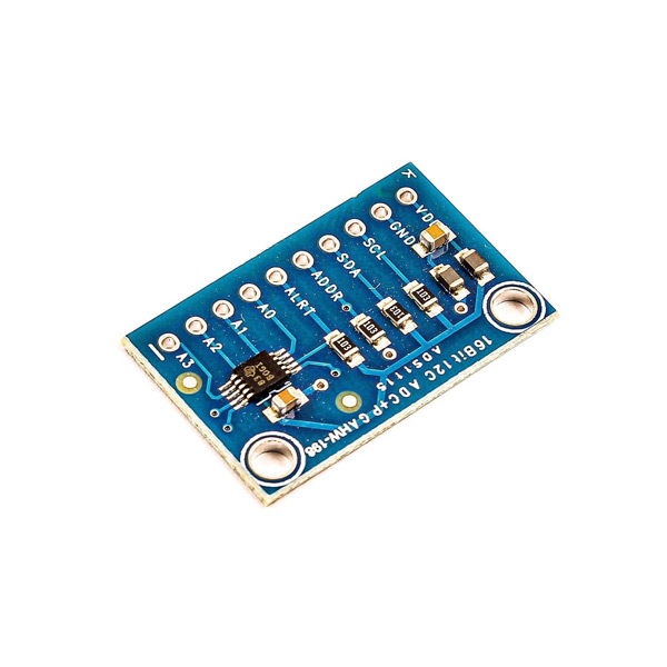
معرفی پایه ها (Pinout) ماژول مبدل آنالوگ به دیجیتال ADS1115
ماژول مبدل آنالوگ به دیجیتال ADS1115 دارای 10 پایه به شرح زیر است:
• VCC: تغذیه ماژول
• GND: زمین
• SLC: همزمان سازی برای پروتکل I2C
• SDA: اطلاعات برای پروتکل I2C
• ADDR: تنظیم آدرس پروتکل I2C
• ALRT: وقفه آماده شدن اطلاعات
• A0: ورودی آنالوگ اول
• A1: ورودی آنالوگ دوم
• A2: ورودی آنالوگ سوم
• A3: ورودی آنالوگ چهارم

لوازمی که به آن احتیاج دارید
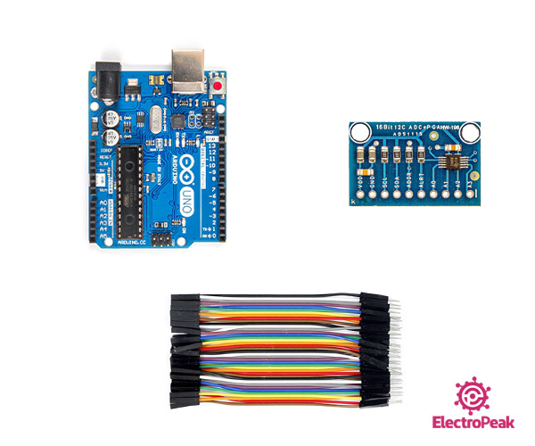
قطعات مورد نیاز
نرم افزارهای مورد نیاز
راهاندازی ماژول مبدل آنالوگ به دیجیتال ADS1115 با آردوینو
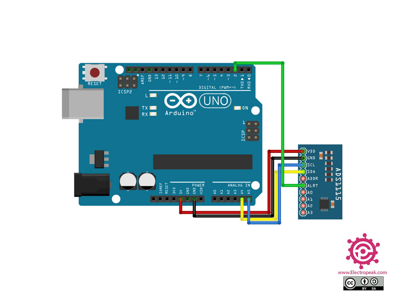
گام اول: سیم بندی
مطابق مدار زیر، ماژول را به آردوینو وصل کنید.
گام دوم: نصب کتابخانه
کتابخانه زیر را بر آردوینوی خود نصب کنید.
https://github.com/jrowberg/i2cdevlib/tree/master/Arduino/ADS1115
توجه
اگر نیاز به راهنمایی بیشتر برای نصب کتابخانه بر روی آردوینو دارید، می توانید به آموزش نصب کتابخانه بر آردوینو مراجعه کنید.
نکته
برای اندازه گیری ولتاژ های دقیق تر باید مقدار Gain را تغییر دهید و با انجام این کار حداکثر ولتاژ قابل نمایش نیز کمتر می شود. مقادیر Gain را می توانید با توجه به جدول زیر انتخاب کنید.
| Gain value | Max Voltage |
|---|---|
| ADS1115_PGA_6P144 | ±6.144V |
| ADS1115_PGA_4P096 | ±4.096V |
| ADS1115_PGA_2P048 | ±2.048V |
| ADS1115_PGA_1P024 | ±1.024V |
| ADS1115_PGA_0P512 | ±0.512V |
| ADS1115_PGA_0P256 | ±0.256V |
گام سوم: کد
کد زیر را روی برد آردوینوی خود آپلود کنید.
/*
  Modify on May 16, 2021
  Modify by MohammedDamirchi base of https://github.com/jrowberg/i2cdevlib/tree/master/Arduino/ADS1115
  https://electropeak.com/learn/
*/


// I2C device class (I2Cdev) demonstration Arduino sketch for ADS1115 class
// Example of reading two differential inputs of the ADS1115 and showing the value in mV
// 2016-03-22 by Eadf (https://github.com/eadf)
// Updates should (hopefully) always be available at https://github.com/jrowberg/i2cdevlib
//
// Changelog:
//     2016-03-22 - initial release

/* ============================================
I2Cdev device library code is placed under the MIT license
Copyright (c) 2011 Jeff Rowberg

Permission is hereby granted, free of charge, to any person obtaining a copy
of this software and associated documentation files (the "Software"), to deal
in the Software without restriction, including without limitation the rights
to use, copy, modify, merge, publish, distribute, sublicense, and/or sell
copies of the Software, and to permit persons to whom the Software is
furnished to do so, subject to the following conditions:

The above copyright notice and this permission notice shall be included in
all copies or substantial portions of the Software.

THE SOFTWARE IS PROVIDED "AS IS", WITHOUT WARRANTY OF ANY KIND, EXPRESS OR
IMPLIED, INCLUDING BUT NOT LIMITED TO THE WARRANTIES OF MERCHANTABILITY,
FITNESS FOR A PARTICULAR PURPOSE AND NONINFRINGEMENT. IN NO EVENT SHALL THE
AUTHORS OR COPYRIGHT HOLDERS BE LIABLE FOR ANY CLAIM, DAMAGES OR OTHER
LIABILITY, WHETHER IN AN ACTION OF CONTRACT, TORT OR OTHERWISE, ARISING FROM,
OUT OF OR IN CONNECTION WITH THE SOFTWARE OR THE USE OR OTHER DEALINGS IN
THE SOFTWARE.
===============================================
*/

#include "ADS1115.h"

ADS1115 adc0(ADS1115_DEFAULT_ADDRESS);

// Wire ADS1115 ALERT/RDY pin to Arduino pin 2
const int alertReadyPin = 2;

void setup() {
    //I2Cdev::begin();  // join I2C bus
    Wire.begin();
    Serial.begin(115200); // initialize serial communication

    Serial.println("Testing device connections...");
    Serial.println(adc0.testConnection() ? "ADS1115 connection successful" : "ADS1115 connection failed");

    adc0.initialize(); // initialize ADS1115 16 bit A/D chip

    // We're going to do single shot sampling
    adc0.setMode(ADS1115_MODE_SINGLESHOT);

    // Slow things down so that we can see that the "poll for conversion" code works
    adc0.setRate(ADS1115_RATE_250);

    // Set the gain (PGA) +/- 6.144v
    // Note that any analog input must be higher than –0.3V and less than VDD +0.3
    adc0.setGain(ADS1115_PGA_6P144);
    // ALERT/RDY pin will indicate when conversion is ready

    pinMode(alertReadyPin,INPUT_PULLUP);
    adc0.setConversionReadyPinMode();

    // To get output from this method, you'll need to turn on the
    //#define ADS1115_SERIAL_DEBUG // in the ADS1115.h file
    #ifdef ADS1115_SERIAL_DEBUG
    adc0.showConfigRegister();
    Serial.print("HighThreshold="); Serial.println(adc0.getHighThreshold(),BIN);
    Serial.print("LowThreshold="); Serial.println(adc0.getLowThreshold(),BIN);
    #endif
}

/** Poll the assigned pin for conversion status
 */
void pollAlertReadyPin() {
  for (uint32_t i = 0; i<100000; i++)
    if (!digitalRead(alertReadyPin)) return;
   Serial.println("Failed to wait for AlertReadyPin, it's stuck high!");
}

void loop() {

    // The below method sets the mux and gets a reading.
    adc0.setMultiplexer(ADS1115_MUX_P0_NG);
    adc0.triggerConversion();
    pollAlertReadyPin();
    Serial.print("A0: "); Serial.print(adc0.getMilliVolts(false)); Serial.print("mV\t");

    adc0.setMultiplexer(ADS1115_MUX_P1_NG);
    adc0.triggerConversion();
    pollAlertReadyPin();
    Serial.print("A1: "); Serial.print(adc0.getMilliVolts(true)); Serial.print("mV\t");

    adc0.setMultiplexer(ADS1115_MUX_P2_NG);
    adc0.triggerConversion();
    pollAlertReadyPin();
    Serial.print("A2: "); Serial.print(adc0.getMilliVolts(true)); Serial.print("mV\t");

    adc0.setMultiplexer(ADS1115_MUX_P3_NG);
    // Do conversion polling via I2C on this last reading:
    Serial.print("A3: "); Serial.print(adc0.getMilliVolts(true)); Serial.print("mV");

    Serial.println(digitalRead(alertReadyPin));
    delay(500);
*/
این کد جهت تست مقادیر دریافتی از پایه های A0~A3 میباشد.

Comments (2)
سلام معمولا ادرس پیش فرض این ماژول چیه؟
با سلام
به صورت نرمال 0x48 می باشد که با استفاده از ADDR این آدرس را تغییر بدهید. بهتر است قبل از استفاده از برد با استفاده از کد I2CSanner این موضوع را بررسی بنمایید.