

ویژگی های ماژول مبدل آنالوگ به دیجیتال ADS1118
در بیشتر میکروکنترلرها مبدل آنالوگ به دیجیتال وجود دارد اما این مبدل از دقت بالایی برخوردار نیست. در بسیاری از پروژهها نیاز است مقادیر آنالوگ با دقت بالا اندازهگیری شود، یا سطح ولتاژ مقادیر آنالوگ در محدوده اندازهگیری میکروکنترلر نمیباشد و یا میکروکنترلر مورد استفاده مبدل آنالوگ به دیجیتال ندارد. در این موارد از IC های جانبی مبدل آنالوگ به دیجیتال استفاده میگردد.
آی سی ADS1118 یکی از انواع آیسیهای مبدل آنالوگ به دیجیتال میباشد که دارای دقت 16 بیتی است و حداکثر ولتاژ 7 ولت را اندازهگیری میکند. این ماژول اختلاف ولتاژ بین 2 پایه ورودی را اندازهگیری میکند.
جهت دریافت دیتاشیت ADS1118 اینجا کلیک کنید.
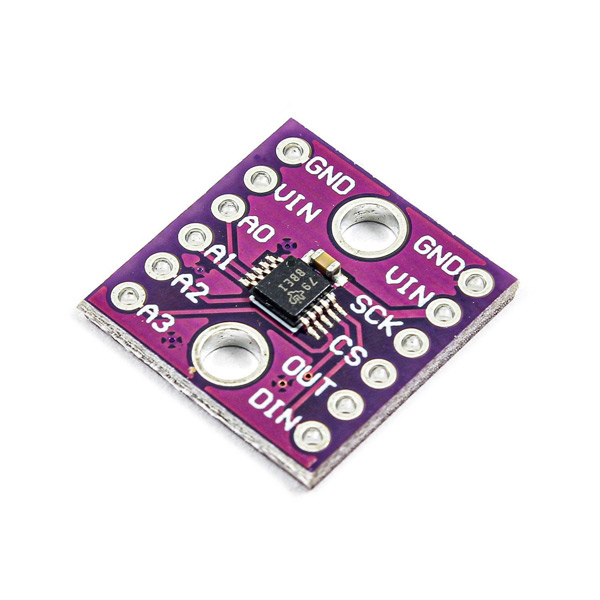
معرفی پایه ها (Pinout) ماژول مبدل آنالوگ به دیجیتال ADS1118
ماژول مبدل آنالوگ به دیجیتال ADS1118 دارای 10 پایه به شرح زیر است:
• 3.3: تغذیه ماژول
• GND: زمین
• SCK: همزمان سازی برای پروتکل SPI
• MOSI: خط ارسالی اطلاعات برای پروتکل SPI
• MISO: خط دریافتی اطلاعات برای پروتکل SPI
• CS: انتخاب دستگاه های زیر مجموعه برای پروتکل SPI
• A0: ورودی آنالوگ اول
• A0: ورودی آنالوگ دوم
• A0: ورودی آنالوگ سوم
• A0: ورودی آنالوگ چهارم

لوازمی که به آن احتیاج دارید
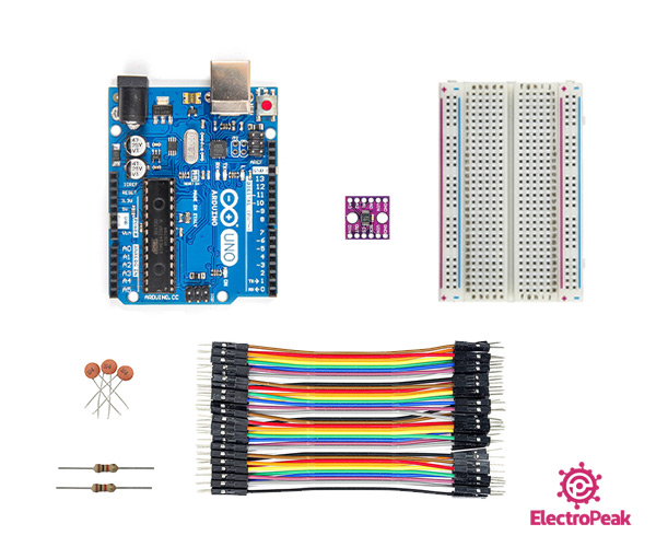
قطعات مورد نیاز
نرم افزارهای موردنیاز
راهاندازی ماژول مبدل آنالوگ به دیجیتال ADS1118 با استفاده از آردوینو
گام اول: سیم بندی
مطابق مدار زیر، ماژول را به آردوینو وصل کنید.
نکته
برای تست ماژول از یک پتاسیومتر استفاده شده است که میتوانید آن را با سنسور دما یا سایر سنسورهای دیگر تعویض کنید.

گام دوم: نصب کتابخانه
کتابخانه زیر را بر آردوینوی خود نصب کنید.
توجه
اگر نیاز به راهنمایی بیشتر برای نصب کتابخانه بر روی آردوینو دارید، می توانید به آموزش نصب کتابخانه بر آردوینو مراجعه کنید.
نکته
برای اندازهگیری ولتاژهای دقیقتر باید مقدار setFullScaleRange را تغییر دهید و با انجام این کار حداکثر ولتاژ قابل نمایش نیز کمتر میشود.
| Gain value | Max Voltage |
|---|---|
| FSR_6144 | ±6.144V |
| FSR_4096 | ±4.096V |
| FSR_2048 | ±2.048V |
| FSR_1024 | ±1.024V |
| FSR_0512 | ±0.512V |
| FSR_0256 | ±0.256V |
گام سوم: کد
کد زیر را روی برد آردوینوی خود آپلود کنید.
/*
Modify on May 16, 2021
  Modify by MohammedDamirchi base of https://github.com/denkitronik/ADS1118
  https://electropeak.com/learn/
*/


/**
*  Example for Arduino Library for Texas Instruments ADS1118 - 16-Bit Analog-to-Digital Converter with
*  Internal Reference and Temperature Sensor
*
*  @author Alvaro Salazar <alvaro@denkitronik.com>
*  http://www.denkitronik.com
*
*/

#include "ADS1118.h"
#include <SPI.h>

//Definition of the Arduino pin to be used as the chip select pin (SPI CS pin). Example: pin 5
#define CS 10

//Creating an ADS1118 object (object's name is ads1118)
ADS1118 ads1118(CS);


void setup(){
    Serial.begin(115200);
    ads1118.begin(); //Initialize the ADS1118. Default setting: PULLUP RESISTOR, ADC MODE, RATE 8SPS, SINGLE SHOT, ±0.256V, DIFFERENTIAL AIN0-AIN1

    /*
     *  EXAMPLES:
     *  The lines above in this method are needed only if you want to change the default setting. Use them to fit your needs
     *  If you need to take care of noise and the ENOB (Effective Number of Bits) see the tables at the end of this file
     */

    /* Changing the sampling rate.
       Available values: RATE_8SPS, RATE_16SPS, RATE_32SPS, RATE_64SPS, RATE_128SPS, RATE_250SPS, RATE_475SPS, RATE_860SPS */
    ads1118.setSamplingRate(ads1118.RATE_16SPS);             //Using the setter method to change the sampling rate
    //ads1118.configRegister.bits.rate=ads1118.RATE_8SPS;   //Driving the config register directly. Uncomment if you want to use this way

    /* Changing the input selected.
       Available values: Diferential inputs: DIFF_0_1, DIFF_0_3, DIFF_1_3, DIFF_2_3.
                         Single ended input: AIN_0, AIN_1, AIN_2, AIN_3*/
    ads1118.setInputSelected(ads1118.DIFF_0_1);             //Using the setter method to change the input selected
    //ads1118.configRegister.bits.mux=ads1118.DIFF_0_1;     //Driving the config register directly. Uncomment if you want to use this way

    /* Changing the full scale range.
       Available values: FSR_6144 (±6.144V)*, FSR_4096(±4.096V)*, FSR_2048(±2.048V), FSR_1024(±1.024V), FSR_0512(±0.512V), FSR_0256(±0.256V).
       (*) No more than VDD + 0.3 V must be applied to this device. */
    ads1118.setFullScaleRange(ads1118.FSR_0256);            //Using the setter method to change the full scale range
    //ads1118.configRegister.bits.pga=ads1118.FSR_0256;     //Driving the config register directly. Uncomment if you want to use this way


    /* Setting to continuous conversion mode */
    ads1118.setContinuousMode();                            //Using the setter method to set it to continuous mode
    //ads1118.configRegister.bits.operatingMode=CONTINUOUS; //Driving the config register directly. Uncomment if you want to use this way

    /* Setting to single shot conversion mode */
    ads1118.setSingleShotMode();                            //Using the setter method to set it to "single shot conversion and power down" mode
    //ads1118.configRegister.bits.operatingMode=SINGLE_SHOT;//Driving the config register directly. Uncomment if you want to use this way

    /* Disabling the pull-up resistor */
    ads1118.disablePullup();                                //Using the setter method to disable the pull-up resistor in Dout
    //ads1118.configRegister.bits.pullUp=PULLUP;            //Driving the config register directly. Uncomment if you want to use this way

    /* Enabling the pull-up resistor */
    ads1118.enablePullup();                                 //Using the setter method to enable the pull-up resistor in Dout
    //ads1118.configRegister.bits.pullUp=NO_PULLUP;         //Driving the config register directly. Uncomment if you want to use this way
}


void loop(){
//    Serial.println(String(ads1118.getTemperature(),6)+" C"); //Getting temperature
    Serial.println(String(ads1118.getMilliVolts(),10)+"mV"); //Getting millivolts measured in the input selected

    //Serial.println(String(ads1118.getMilliVolts(ads1118.DIFF_0_1),10)+"mV"); //Specifying the input to be selected

    delay(200); //You can use a delay to save power. The ADS1118 will be in power down state during all the delay time. Optional

}

/*
              Table 1. Noise in μVRMS (μVPP) at VDD = 3.3 V   [1]
                DATA RATE FSR (Full-Scale Range)
  (SPS) ±6.144 V        ±4.096 V     ±2.048 V       ±1.024 V        ±0.512 V        ±0.256 V
  8     187.5 (187.5)   125 (125)    62.5 (62.5)    31.25 (31.25)   15.62 (15.62)   7.81 (7.81)
  16    187.5 (187.5)   125 (125)    62.5 (62.5)    31.25 (31.25)   15.62 (15.62)   7.81 (7.81)
  32    187.5 (187.5)   125 (125)    62.5 (62.5)    31.25 (31.25)   15.62 (15.62)   7.81 (7.81)
  64    187.5 (187.5)   125 (125)    62.5 (62.5)    31.25 (31.25)   15.62 (15.62)   7.81 (7.81)
  128   187.5 (187.5)   125 (125)    62.5 (62.5)    31.25 (31.25)   15.62 (15.62)   7.81 (12.35)
  250   187.5 (252.09)  125 (148.28) 62.5 (84.03)   31.25 (39.54)   15.62 (16.06)   7.81 (18.53)
  475   187.5 (266.92)  125 (227.38) 62.5 (79.08)   31.25 (56.84)   15.62 (32.13)   7.81 (25.95)
  860   187.5 (430.06)  125 (266.93) 62.5 (118.63)  31.25 (64.26)   15.62 (40.78)   7.81 (35.83)


      Table 2. ENOB from RMS Noise (Noise-Free Bits from Peak-to-Peak Noise) at VDD = 3.3 V
                DATA RATE FSR (Full-Scale Range)
  (SPS)   ±6.144 V    ±4.096 V   ±2.048 V     ±1.024 V    ±0.512 V    ±0.256 V
  8       16 (16)     16 (16)    16 (16)      16 (16)     16 (16)     16 (16)
  16      16 (16)     16 (16)    16 (16)      16 (16)     16 (16)     16 (16)
  32      16 (16)     16 (16)    16 (16)      16 (16)     16 (16)     16 (16)
  64      16 (16)     16 (16)    16 (16)      16 (16)     16 (16)     16 (16)
  128     16 (16)     16 (16)    16 (16)      16 (16)     16 (16)     16 (15.33)
  250     16 (15.57)  16 (15.75) 16 (15.57)   16 (15.66)  16 (15.96)  16 (14.75)
  475     16 (15.49)  16 (15.13) 16 (15.66)   16 (15.13)  16 (14.95)  16 (14.26)
  860     16 (14.8)   16 (14.9)  16 (15.07)   16 (14.95)  16 (14.61)  16 (13.8)


  [1] Texas Instruments, "ADS1118 Ultrasmall, Low-Power, SPIâ„¢-Compatible, 16-Bit Analog-to-Digital
  Converter with Internal Reference and Temperature Sensor", ADS1118 datasheet, SBAS457E [OCTOBER 2010–REVISED OCTOBER 2015].

  Note: This information is taken from http://www.ti.com
        Copyright © 2010–2015, Texas Instruments Incorporated
*/
این کد جهت تست اندازهگیری اختلاف پتانسیل مابین پایه A0 و A1 میباشد.

Comments (2)
سلام
اگر ما 3 عدد این ماژول رو خواستیم همزمان راه اندازی کنیم باید چه تغییری در کد بدهیم؟
با سلام
در مرحله اول پایه CS هر کدام از ماژول ها را باید به پین های مختلفی وصل کنید.
در مرحله دوم در بخش فراخوانی و استفاده از کتاب خانه باید به تعداد ماژول های خود تکرار کنید. یعنی در شروع به جای
ADS1118 ads1118(CS);از کد
ADS1118 ads1118_1(CS1);ADS1118 ads1118_2(CS2);
ADS1118 ads1118_3(CS3);
و داخل کد همه بخش ها را بسته به استفاده از کدام ماژول باید به شماره مورد نظر تغییر بدهید. و مشابه این بخش تکرار کنید.