


ترانسفورماتور افزاینده 15k ولت
- +25 3 % 233٬600 تومان
- +50 6 % 226٬500 تومان
- +100 9 % 219٬500 تومان
- +300 12 % 212٬400 تومان
- +500 15 % 205٬300 تومان


ماژول تقویت کننده ولتاژ 15KV یک مدار ساده و قابل اعتماد است که برای تولید ولتاژ بالا تا حداکثر 15KV طراحی شده است. این ماژول به طور گسترده در آزمایشهای علمی، تجهیزات الکترونیکی و تولید یون منفی استفاده میشود. با استفاده از این ماژول میتوان آرکهای با دمای بالا تولید کرد که به راحتی مواد قابل احتراق را مشتعل میکند و در برخی پروژهها به عنوان فندک پلاسما نیز استفاده میشود.
مشخصات فنی ترانسفورماتور افزاینده 15k ولت
- ولتاژ ورودی: 3.7V-4.2V (حداکثر 12V با تغییر مقاومت فیدبک)
- جریان ورودی: کمتر از 2A
- ولتاژ خروجی: حداکثر 15KV
- جریان خروجی: حداکثر 0.4A
- فاصله جرقه: حداکثر 0.5cm
- ابعاد ماژول: تقریباً 25mm x 15mm x 20mm (طول x عرض x ارتفاع)
- ابعاد ترانسفورمر: 27mm x 16mm x 21mm
ویژگیهای ترانسفورماتور افزاینده 15k ولت
- آرک دمای بالا: تولید آرکهای با دمای بالا که میتوانند به راحتی مواد را مشتعل کنند.
- ساخت ساده: دارای مدار ساده و قابل تولید با قطعات اولیه، مناسب برای علاقمندان به الکترونیک.
- کاربردهای متنوع: استفاده در آزمایشهای علمی، تولید ژنراتور یون منفی، تجهیزات الکترونیکی و ساخت پروژههای کوچک علمی.
نکات نصب و استفاده از ترانسفورماتور افزاینده 15k ولت
- اتصال صحیح سیمها: اطمینان حاصل کنید که سیمهای ضخیم و نازک در دو طرف مدار به درستی متصل شوند.
- تغییر مقاومت فیدبک: اگر از ولتاژ ورودی 12V استفاده میکنید، باید مقاومت فیدبک به میزان 150Ω تا 1.5KΩ افزایش یابد تا از آسیب به ترانزیستور یا ترانسفورمر جلوگیری شود.
- ایمنی: هنگام کار با ولتاژ بالا حتماً اقدامات ایمنی لازم را رعایت کنید تا از آسیب به تجهیزات یا خود جلوگیری کنید.
هشدارها:
- ولتاژ بیش از حد: خروجی ولتاژ نباید از 15KV (فاصله جرقه 1.5cm) تجاوز کند؛ زیرا ممکن است باعث آسیب به ترانسفورمر شود.
- داغی آرک: آرک ایجاد شده دمای بسیار بالایی دارد و میتواند به راحتی کاغذ یا سیمهای نازک را بسوزاند.
- بستهبندی: برای جلوگیری از آسیب به مدار و ترانسفورمر در بلندمدت، پیشنهاد میشود که ماژول با موم عایق یا رزین اپوکسی به طور کامل عایقبندی شود.
ساخت و نصب:
- در تولید ماژول از برد PCB با ابعاد 4.2cm x 3.2cm x 0.16cm استفاده میشود. هنگام نصب قطعات بر روی برد، باید توجه کنید که سیمهای ضخیم و نازک به درستی در جای خود قرار گیرند و از اتصالات کوتاه جلوگیری شود.
Features:
◦This product is a booster coil production suite, the circuit is simple and reliable, with a professional line drawings, electronic research convenience enthusiasts
◦Uses: high school science experiment, electronic equipment, negative ion generator, scientific small production. This circuit is generated when the stable high frequency arc, high temperature, can easily ignite combustible materials, so it was called the plasma lighters
Parameter:
◦15KV transformer outside dimensions of approximately: 27×16×21mm
◦Input voltage: DC 3.7V-4.2V (limit 12v, easy to damage not recommended, this transformer is equally applicable to 12V input voltage, but requires a corresponding increase in the base of the feedback resistor to about 150Ω ~ 1.5KΩ, its resistance should be large to replace a small adjustment, or burned transistor or transformer)
◦Input Current: <2A
◦Output voltage: approximately 15KV (please pay attention to safety when used)
◦Output Current: ≤0.4A
◦High voltage bipolar ignition distance: ≤0.5 cm
◦When the product input termination 3.7V-4.2V power supply, the secondary high voltage output is not connected to high-voltage rectifier diodes and capacitors, output terminals levels ≤1.5cm long can produce purple high temperature arc, no crackling, but the temperature is very high , you can easily and instantly point cigarette paper, or even very thin wire burned Sparks (such as junior high school chemistry experiment thin wire in oxygen combustion scene, but not as good as oxygen so intense.)
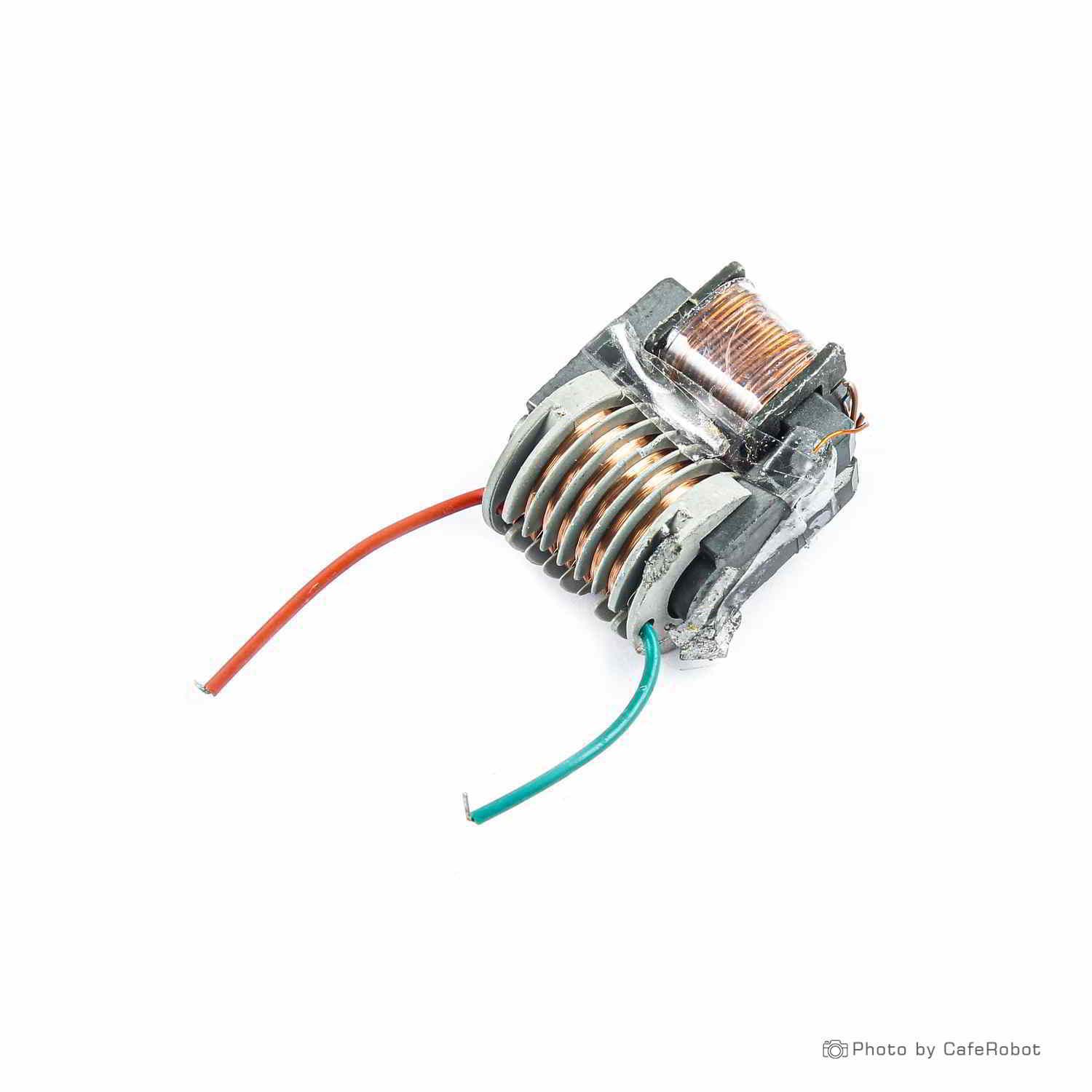
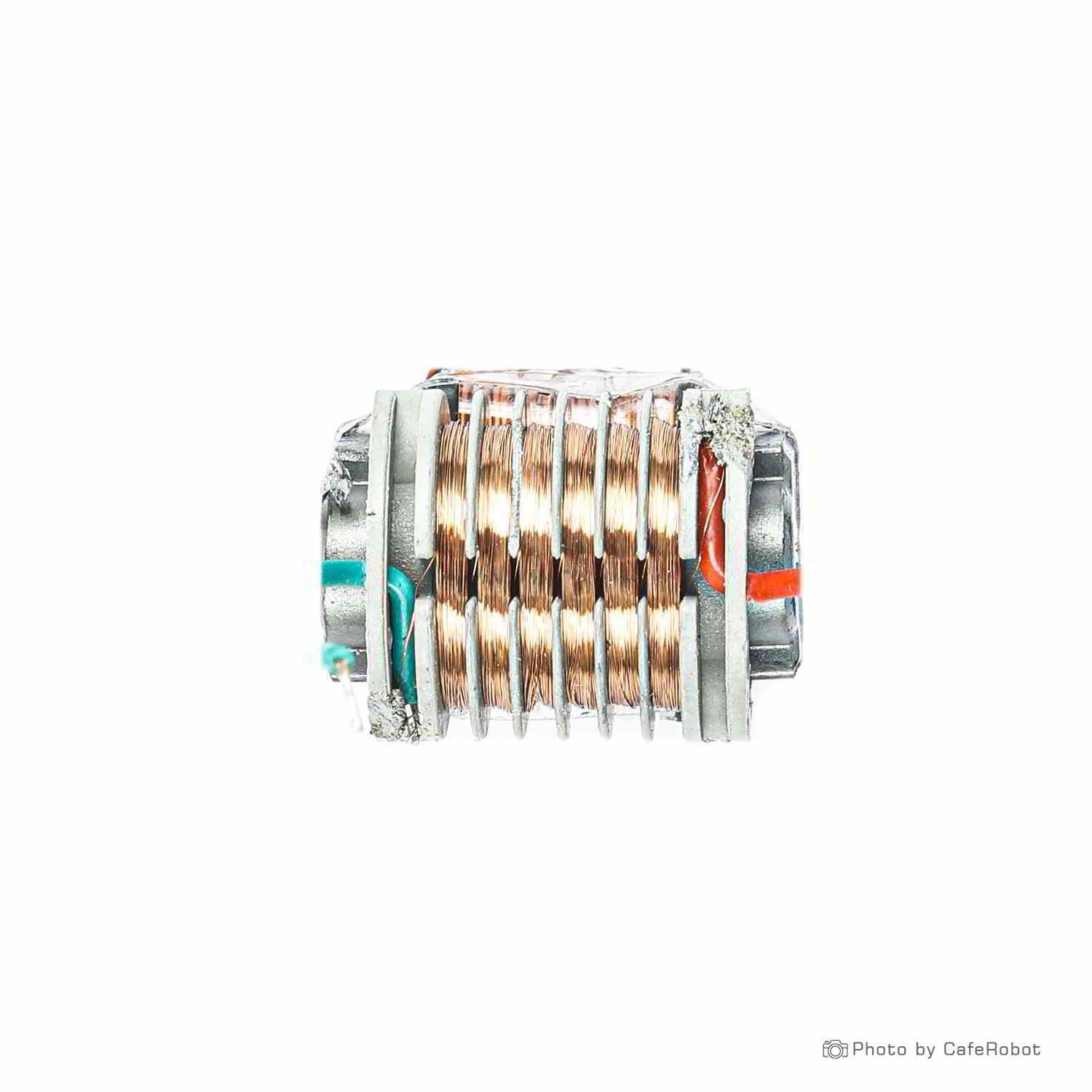
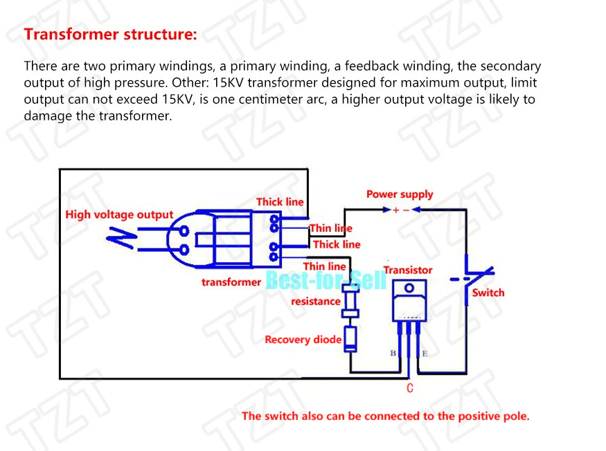
Transformer structure:
There are two primary windings, a primary winding, a feedback winding, the secondary output of high pressure. Other: 15KV transformer designed for maximum output, limit output can not exceed 15KV, is one centimeter arc, a higher output voltage is likely to damage the transformer.
PCB board size: 4.2CM * 3.2CM * 0.16CM;

Installation Notes:
1). With the PCB board parts better production, in which the transformer line of thick line and thin line, this should pay attention to the other components by the board of silk symbols and parameters of welding on the line. Transformer board has done three pads, in which the middle of the pad hole is relatively large, the hole at the same time welding a thick enameled wire and a thin enameled wire, thick enameled wire and fine enameled wire do not use the same side, such as with the left Thick lines and the right side of the thin wire into or with the left side of the thin line and the right side of the thick line welding into, in short, do not use the same side of the thick lines and thin lines can be.

2). In order to prevent the output 2-wire distance too far, resulting in no-load, you can weld a 3P pin at the output.

3). After the success of the production, if the output access to a high-voltage capacitor and three high-voltage rectifier composed of voltage doubler circuit, you can produce DC high voltage, you can make anion generator, wiring diagram is as follows:
Note:
1. The high-voltage winding of the transformer is in the inner layer. It is wound by a segmented bobbin and encapsulated in epoxy resin. The low-voltage winding is in the outer layer. Please do not mistake the high-voltage winding and the low-voltage winding for the same winding method.
2. This circuit produces a stable high-frequency arc when operating. The temperature is extremely high and it can easily ignite combustibles.
3. When the secondary high voltage output of the transformer is not connected to the high voltage rectifier diode and capacitor, the output is high frequency and high voltage electricity. When it is punctured in the air, it is a light purple arc with no hum, but the temperature is very high and the paper can be easily ignited. , Even fine iron wire (just like the scene of the burning of fine iron wire in oxygen during the junior high school chemistry experiment, but not as intense as in oxygen).
4. If the output terminal is connected to several voltage-compression circuits composed of several high-voltage capacitors and high-voltage rectifiers, DC high voltage can be generated, and negative ion generators can be produced.
5. This transformer is also suitable for 12V voltage, but it is necessary to increase the base feedback resistance to about 150Ω~1.5KΩ. The resistance value should be adjusted from large to small, and it should not be too small, otherwise it will not burn the transistor or transformer. Should be too large, affect the output effect too much or make the triode work in non-switching state and generate heat seriously.
6. The transformer is designed to have a maximum output of 15KV. The maximum limit output must not exceed 15KV, that is, a 1.5cm arc. Higher output voltages may damage the transformer. For reliable and long-term continuous work, it is recommended to completely seal it with insulating wax or epoxy resin. Work is prohibited when no work is done.